Seismology in Friendswood, Texas, USA
Frank Cooper's Public Seismic Network Station
Mail Questions and/or Comments to: Frank Cooper@Prodigy.Net
NEAR REAL-TIME HORIZONTAL SEISMOGRAPH HELICORDER
Updates every 5 minutes --- mouse click "refresh" for the latest image.
This near-real-time recording was made with my oldest
Lehman horizontal seismograph FC1 (set up in my garage) and Larry Cochrane's WinSDR datalogger software and hardware.
I constructed
this sensor in January of 1997 and it has been in continuous operation since then. This sensor is capable of
detecting any strong earthquake on earth. It is most sensitive to long seismic waves. If you see an earthquake
recorded on the helicorder, mouse click on Current Quakes World Wide to see where the quake occurred.
Current Quakes World Wide To see
other PSN helicorders
mouse click on Near Live PSN Helicorders
This should play within several seconds.
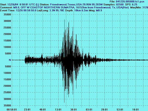
The 9.0 Sumatra earthquake on 12/26/04 as recorded by my garage horizontal seismograph FC1
The horizontal seismograph is most sensitive to long waves and the long waves are shown most prominent.
The four hour seismogram is shown very compressed. When uncompressed and expanded it would easily
cover six feet of computer paper.
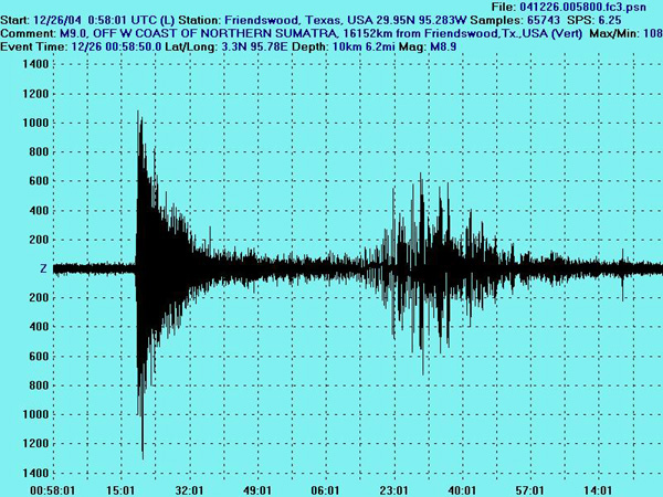
The 9.0 Sumatra earthquake on 12/26/04 as recorded by my garage vertical seismograph FC3
The vertical seismograph is most sensistive to P waves (the earliest waves recorded)
so they are shown most prominent. The four hour seismogram is shown very compressed. When uncompressed and
expanded it would easily cover six feet of computer paper.

MY EARTHQUAKE RECORDING STATION
The two chart recorders on the left using a seismic amp (rectangular box above CRT) designed and
constucted by my son Stan, record the 7.5 magnitude NORTHWEST OF KURIL ISLANDS earthquake on 11/17/02.
A computer with a 2 ghz cpu stores the earthquake data with the use of Larry
Cochrane's WinSDR data logger. Larry maintains the Redwood City (Calif.) Public Seismic Network
(web address near the bottom of this page). The computer monitor shows the traces of the quake from my two seismic
sensors [modified Lehman (FC1) and T Max (FC2). Traces from a vertical sensor, FC3, are not shown.
The wooden enclosure on the right is a speaker for WWV time signals, variable
resistors to control amplification for seismic signals and a galvanometer to monitor the output.
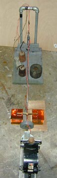
The Modified Lehman --- Continuously in Operation Since January, 1997
 The Sensor
Cover
The Sensor
Cover
The Seismograph sensor is housed in a cover made of Celotex to keep out unwanted drafts.
Two see-thru plastic windows have been incorporated in the top. The sensor, which I constructed in January, 1997,
is in my garage.
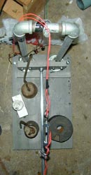
A View of the Sensor(FC1)from Above.
The weights are kept on the base plate to keep it from tipping over.
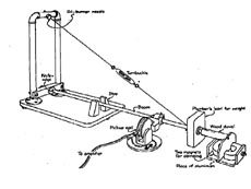
The drawing on the right was taken from an article in Scientific American published in July,
1979, in The Amateur Scientist column. My Lehman was modeled after this article. I have modified a few
things. Dampening of my Lehman is accomplished with brass paddles in power steering fluid and not with magnetic
dampening. I have mounted the pick-up coil at the end of the boom. The original Lehman did not mount the pick-up
coil on the boom. The original Lehman article can be found at "Build Your
Own Seismograph Station."
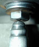
The Pivot Point
I am using John Cole's method of inserting a ball bearing at the pivot point of the boom. The ball
bearing in the boom end rests upon a polished bolt head. By eliminating a major part of the friction at the pivot
point, the period of my Lehman pendulum was increased from 12 seconds to 16 seconds.
I had obtained the 12 second period by grinding the boom end to a point and then inserted it into a
V shaped indentation in the bolt head. John Cole has made a significant contribution with his method.
The coil Moves in the Gap of the Magnet
A 14,000 turn coil is positioned within the gap of a war-surplus magnet. The weight is made of
five pounds of lead. Dampening is accomplished by two brass paddles immersed in the two containers power steering
fluid. As can be seen in the photo, the coil is not centered but is off-set within the gap of the magnet. I have
discovered that the seismograph sensor is much more sensitive when the coil is not centered.
Click on the picture for a much larger image.
The Vertical
John Cole is pictured on the porch of my house setting up a vertical sensor that he presented
to me as a gift. My postings on PSN with this vertical are labeled FC3. The cover is in the background.
John has constructed and tested several of these vertical sensors. He and I talk nightly on 70 cm Amateur Television
and discuss each sensor as he is constructing it. He listens to my opinions and in some cases makes use of my input.
John worked on the design for this vertical for months. He found that his verticals did not work
very well using store bought springs and he began winding his own. They were an instant success. He also winds his
own coils. The sensor uses a 14,000 turn coil made from #34 wire. I first began using double paddles in power steering
fluid for damping in 1997 and John continues the practice. I took apart a very old chart recorder to get the magnet.
The period of the vertical is most sensitive in the range of one to several seconds.
The Horizontal T-Max

The T Max (left) was conceived and constructed by John Cole of Pearland, Texas, USA. A closer view of the T Max steel
base is on the right. John named the sensor for the T shape of the base. He presented the sensor to me as a gift and
it is now installed on my garage floor next to my modified Lehman.
This near-real-time recording was made with my oldest Lehman horizontal seismograph FC1 (set up in my garage) and Larry Cochrane's WinSDR datalogger software and hardware. I constructed this sensor in January of 1997 and it has been in continuous operation since then. This sensor is capable of detecting any strong earthquake on earth. It is most sensitive to long seismic waves. If you see an earthquake recorded on the helicorder, mouse click on Current Quakes World Wide to see where the quake occurred. Current Quakes World Wide To see other PSN helicorders mouse click on Near Live PSN Helicorders
This should play within several seconds.
The 9.0 Sumatra earthquake on 12/26/04 as recorded by my garage horizontal seismograph FC1
The horizontal seismograph is most sensitive to long waves and the long waves are shown most prominent. The four hour seismogram is shown very compressed. When uncompressed and expanded it would easily cover six feet of computer paper.
The 9.0 Sumatra earthquake on 12/26/04 as recorded by my garage vertical seismograph FC3
The vertical seismograph is most sensistive to P waves (the earliest waves recorded) so they are shown most prominent. The four hour seismogram is shown very compressed. When uncompressed and expanded it would easily cover six feet of computer paper.
MY EARTHQUAKE RECORDING STATION
The two chart recorders on the left using a seismic amp (rectangular box above CRT) designed and
constucted by my son Stan, record the 7.5 magnitude NORTHWEST OF KURIL ISLANDS earthquake on 11/17/02.
A computer with a 2 ghz cpu stores the earthquake data with the use of Larry
Cochrane's WinSDR data logger. Larry maintains the Redwood City (Calif.) Public Seismic Network
(web address near the bottom of this page). The computer monitor shows the traces of the quake from my two seismic
sensors [modified Lehman (FC1) and T Max (FC2). Traces from a vertical sensor, FC3, are not shown.
The wooden enclosure on the right is a speaker for WWV time signals, variable
resistors to control amplification for seismic signals and a galvanometer to monitor the output.
The Modified Lehman --- Continuously in Operation Since January, 1997
The Sensor
Cover
The Seismograph sensor is housed in a cover made of Celotex to keep out unwanted drafts.
Two see-thru plastic windows have been incorporated in the top. The sensor, which I constructed in January, 1997,
is in my garage.
A View of the Sensor(FC1)from Above.
The weights are kept on the base plate to keep it from tipping over.
The drawing on the right was taken from an article in Scientific American published in July,
1979, in The Amateur Scientist column. My Lehman was modeled after this article. I have modified a few
things. Dampening of my Lehman is accomplished with brass paddles in power steering fluid and not with magnetic
dampening. I have mounted the pick-up coil at the end of the boom. The original Lehman did not mount the pick-up
coil on the boom. The original Lehman article can be found at "Build Your
Own Seismograph Station."
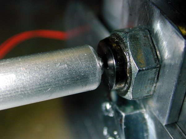
The Pivot Point
I am using John Cole's method of inserting a ball bearing at the pivot point of the boom. The ball
bearing in the boom end rests upon a polished bolt head. By eliminating a major part of the friction at the pivot
point, the period of my Lehman pendulum was increased from 12 seconds to 16 seconds.
I had obtained the 12 second period by grinding the boom end to a point and then inserted it into a
V shaped indentation in the bolt head. John Cole has made a significant contribution with his method.
The coil Moves in the Gap of the Magnet
The two chart recorders on the left using a seismic amp (rectangular box above CRT) designed and
constucted by my son Stan, record the 7.5 magnitude NORTHWEST OF KURIL ISLANDS earthquake on 11/17/02.
A computer with a 2 ghz cpu stores the earthquake data with the use of Larry
Cochrane's WinSDR data logger. Larry maintains the Redwood City (Calif.) Public Seismic Network
(web address near the bottom of this page). The computer monitor shows the traces of the quake from my two seismic
sensors [modified Lehman (FC1) and T Max (FC2). Traces from a vertical sensor, FC3, are not shown.
The wooden enclosure on the right is a speaker for WWV time signals, variable
resistors to control amplification for seismic signals and a galvanometer to monitor the output.
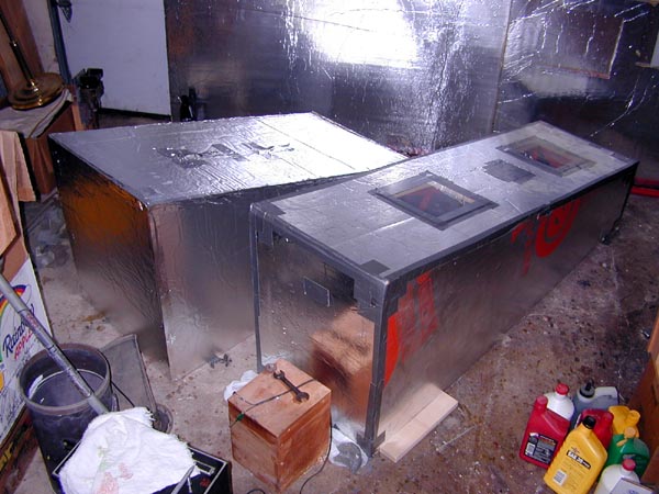
The Sensor
Cover
The Seismograph sensor is housed in a cover made of Celotex to keep out unwanted drafts. Two see-thru plastic windows have been incorporated in the top. The sensor, which I constructed in January, 1997, is in my garage.
A View of the Sensor(FC1)from Above.
The weights are kept on the base plate to keep it from tipping over. The drawing on the right was taken from an article in Scientific American published in July,
1979, in The Amateur Scientist column. My Lehman was modeled after this article. I have modified a few
things. Dampening of my Lehman is accomplished with brass paddles in power steering fluid and not with magnetic
dampening. I have mounted the pick-up coil at the end of the boom. The original Lehman did not mount the pick-up
coil on the boom. The original Lehman article can be found at "Build Your
Own Seismograph Station."
The Pivot Point
I am using John Cole's method of inserting a ball bearing at the pivot point of the boom. The ball bearing in the boom end rests upon a polished bolt head. By eliminating a major part of the friction at the pivot point, the period of my Lehman pendulum was increased from 12 seconds to 16 seconds.
I had obtained the 12 second period by grinding the boom end to a point and then inserted it into a V shaped indentation in the bolt head. John Cole has made a significant contribution with his method.
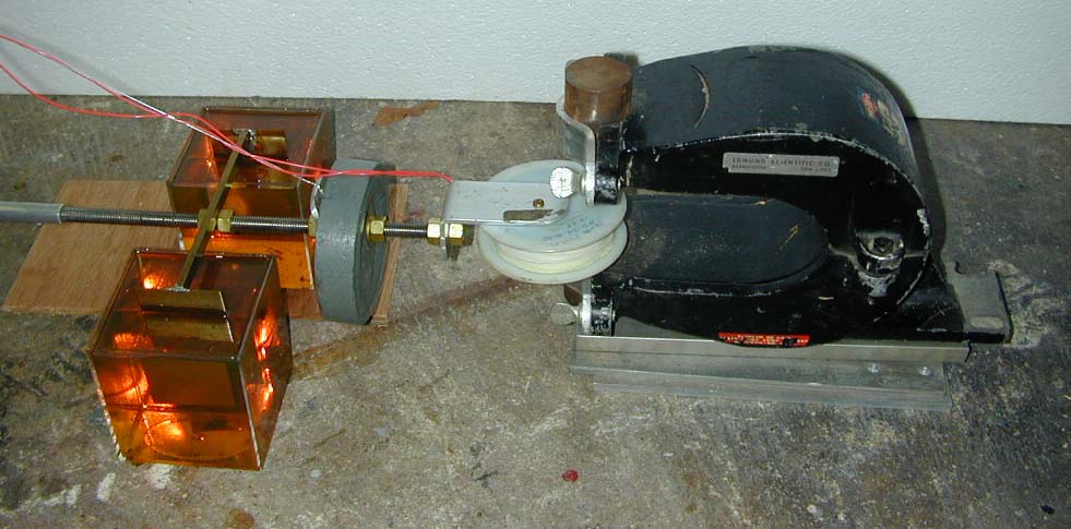
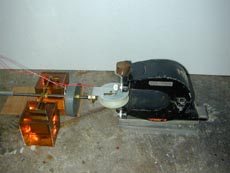
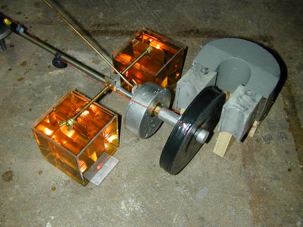
The coil Moves in the Gap of the Magnet
A 14,000 turn coil is positioned within the gap of a war-surplus magnet. The weight is made of five pounds of lead. Dampening is accomplished by two brass paddles immersed in the two containers power steering fluid. As can be seen in the photo, the coil is not centered but is off-set within the gap of the magnet. I have discovered that the seismograph sensor is much more sensitive when the coil is not centered. Click on the picture for a much larger image.
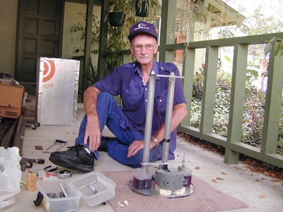
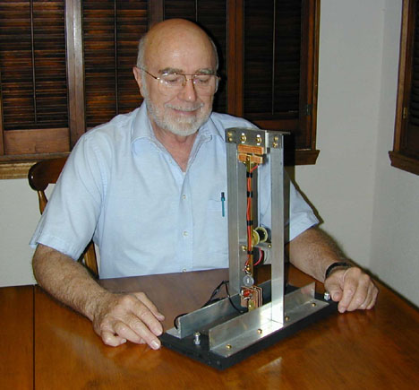
The Vertical
John Cole is pictured on the porch of my house setting up a vertical sensor that he presented
to me as a gift. My postings on PSN with this vertical are labeled FC3. The cover is in the background.
John has constructed and tested several of these vertical sensors. He and I talk nightly on 70 cm Amateur Television
and discuss each sensor as he is constructing it. He listens to my opinions and in some cases makes use of my input.
John worked on the design for this vertical for months. He found that his verticals did not work
very well using store bought springs and he began winding his own. They were an instant success. He also winds his
own coils. The sensor uses a 14,000 turn coil made from #34 wire. I first began using double paddles in power steering
fluid for damping in 1997 and John continues the practice. I took apart a very old chart recorder to get the magnet.
The period of the vertical is most sensitive in the range of one to several seconds.
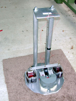
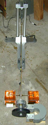
The Horizontal T-Max
The T Max (left) was conceived and constructed by John Cole of Pearland, Texas, USA. A closer view of the T Max steel base is on the right. John named the sensor for the T shape of the base. He presented the sensor to me as a gift and it is now installed on my garage floor next to my modified Lehman.
John Cole does a great deal of experimentation with and construction of amateur teleseismic
earthquake sensors. He usually has several different kinds of sensors under development. John has given and sold
various kinds of detectors for use in public schools as well as
for use by amateurs in a couple of foreign countries and several US states. During our nightly conversations on 70cm
amateur television we frequently talked about the T Max as he was developing it. The name T Max comes from
the shape of the steel base. The base is one solid piece of T-shaped steel and is relatively inexpensive. The solid
steel base eliminates the problems of an expensive large aluminum base. The T Max uses a "Cole Ball Bearing Pivot"
(John developed the idea) at the pivot point of the pendumum rod. Rather than using a wire suspension, John has been
able to use another ball bearing as the suspension. This may be seen in the pictures. By reducing the friction at
the pivot point and at the suspension point, the detection frequency can be appreciably increased.
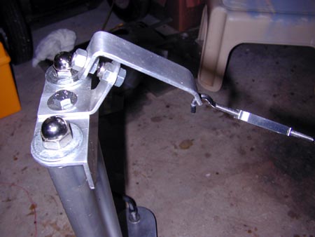
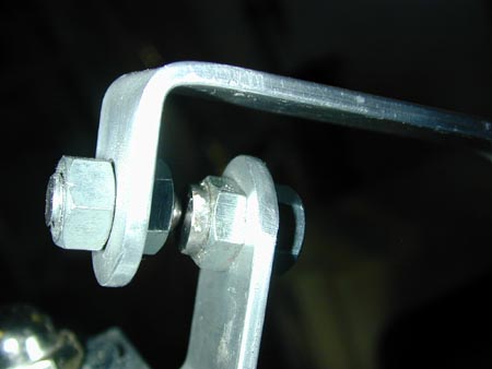
The Cole Ball Bearing
Note the ball bearing inserted into the end of the rod supporting the coil. The nickel chrome ball bearing rests upon a slightly convex nickel chrome polished steel surface. Click on the picture for a much larger image.
The Upper Suspension Nickel Chrome Ball Bearing rests on a slightly convex polished nickel chrome surface. The Nickel chrome steel convex surface is impervious to dimpling or scratching by the ball
Magnet,Coil, and Damping
The powerful magnet is from a very old chart recorder. The gap of the magnet can easily be changed with the two hands. The damping medium is power steering fluid. The double damping paddles are made of brass. The five pound lead pendulum weight was originally poured in a tuna can. There are 17,200 turns of wire in the coil. The coil is wound in such a way that all of the turns of the coil are within the gap of the magnet. I have not seen this vertical orientation of coil within the gap of a magnet in any other amateur seismic detector. Click on the picture for a much larger image.
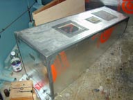
The covers made of Celotex for the two sensors in my garage
Click on the picture for a much larger image.
Click here to go to John Cole's web page
The S-G Sensor
Frank Cooper with his home-made Shackleford-Gunderson seismograph sensor. The S-G is not being used at the present time.
My analog seismograph in 1969
Three area amateur seismologists meet in Pearland, Texas, on July 3, 2000
Three Texas Amateur Seismologists meet in Friendswood, Texas, on January 18, 2001
URL's for Seismograph and Earthquake Information
1.Redwood City Public Seismic Network
4.John Cole's simple way to lengthen the period of a pendulum
5. Public Seismic Network Stations Around the World
7.Don Wheeler's Monroe, La., Earthquake Web page
8.Steve Hammond's "The Public Seismic Network of San Jose"
SEVERAL OTHER COOPER WEB SITES
My Amateur Radio Station W5VID
Home Page Last Modified: Saturday, Jan. 13, 2007
Mail questions and/or comments to:Frank Cooper, fxc@Prodigy.net